
[ad_1]
If you have a digital multimeter handy, it’s fairly easy to test your power supply and rule out power gremlins as the source of your computer’s problems.
Why use a digital multimeter?
Independent power supply testers are great and we always keep one on hand for quick results. They can even give you useful values like the Power Good (PG) value that shows you how quickly your power supply reaches full power; that’s something a multimeter can’t do.

But many people already have digital multimeters on hand and don’t have a PSU tester lying around. So while a PSU tester is nice to have for those little extra features like PG value, you can get almost all of the same data with a more hands-on approach using a multimeter.
How to test your power supply with a digital multimeter
Although using a multimeter is a bit more practical than just plugging in a PSU tester, it’s perfectly safe if you follow a few basic guidelines.
Warning: At no time will we open the power supply itself. Doing so without the proper precautions, knowledge, and tools can give you fatal shock.
Before continuing, we want to emphasize a few points. First, testing your power supply output using the methods described below is very safe. Opening the actual power supply to access the “guts” of the unit is not and will expose you to both line level electricity coming from the wall and the power supply capacitors. Touching the wrong thing inside the PSU’s body has the potential to stop his heart.
If your power supply isn’t working properly, it’s safest to just replace it. Attempting to replace large capacitors, transformers, or other internal power supply components is advanced electronic repair and hardly worth it, given how relatively inexpensive power supplies are.
Get familiar with ATX pinouts
Before we continue, let’s take a look at the 20/24-pin connector to familiarize ourselves with the layout and expected voltages.
We used a handy pin planner created by Reddit user /u/JohnOldman0 to make the diagram below and recommend the tool to anyone planning a custom cable project.

If you hold the connector with the clip facing up, the numbering scheme starts at the bottom left, reads 1-12 on the bottom row, then 13-24 on the top row, for a 24-pin connector. For the purposes of this article, when we use the term “top” we mean “crop.”
For a 20-pin connector, it’s 1-10 and 11-20, respectively, though it’s worth noting that the location of the actual voltages doesn’t change even if the pin number changes. The standard 24-pin ATX connector simply adds an additional 4 pins to the 20-pin connector while retaining the original layout.
Turn off the power supply
If your PSU has a switch, turn it off. If it turns on automatically when plugged into an outlet, unplug it.
Either way, you need to turn off the power supply, not just turn off the computer, before proceeding to the next steps.
Disconnect component cables
You don’t need to remove the power supply from your PC if you’re trying to troubleshoot the power supply instead, but you should unplug all power cables (not just the one you’re testing) to play it safe.
While things are unlikely to go bad enough to damage adjacent components while testing a particular cable, there’s no reason to take any chances when it only takes a few seconds to remove power cables from your GPU, drives, and such.
jump power pin
The first pins to pay attention to are the power supply pin and the adjacent grounds. You must connect the power supply pin (which is pin number 16 on the 24-pin reading, fourth from the left at the top) to the ground pin on either side, as seen on the ATX pinout diagram previous.

You can pass pin 16 to pin 15 or pin 17 (both are ground pins). In the photo above you can see that we have jumped 15 and 16 using a short clip bent into a U shape. The lack of insulation here is not a big deal as the jumper only carries 24 volts and will not touch it during the test .
You can also use a piece of 18 AWG or 16 AWG wire. There are also simple 24-pin ATX power supply jumper tools.
The jumper tool has little numbers stamped on it for each of the pin assignment locations, which is useful if you want a clear indicator of which pin is which without counting. (Although note that some multimeters have probes a bit too short to reach across the bridge, making it difficult to touch the pins and check the voltage.)
Turn on the power supply
Once you’ve connected the power pin to a ground pin, turn the power supply back on. You should hear and see the fan spin on the power supply. Some PSUs have a fan that only spins up briefly during the power-up process and then goes to sleep until the PSU temperature rises, so don’t be alarmed if the fan spins up and then stops a few seconds later.
Testing the pins with your digital multimeter
Testing your power supply with a digital multimeter isn’t too different from using a power supply tester, the main difference is that instead of a little microchip doing the math and giving the thumbs up or thumbs down, you get the hands-on experience of being the microchip and interpreting the data yourself.
At this point you should turn on your multimeter and set the reading to DCV. If your multimeter is “auto ranging” there is no need to do anything, if you need to set a range then set it to 10V.
Place the black multimeric probe on any of the grounded pins. For a standard 24-pin ATX connector, that’s pin 3, 5, 7, 15, 17, 18, 19, or 24. We’ll use pin 15 because its location directly adjacent to the power jumper means it’s easy to identify.
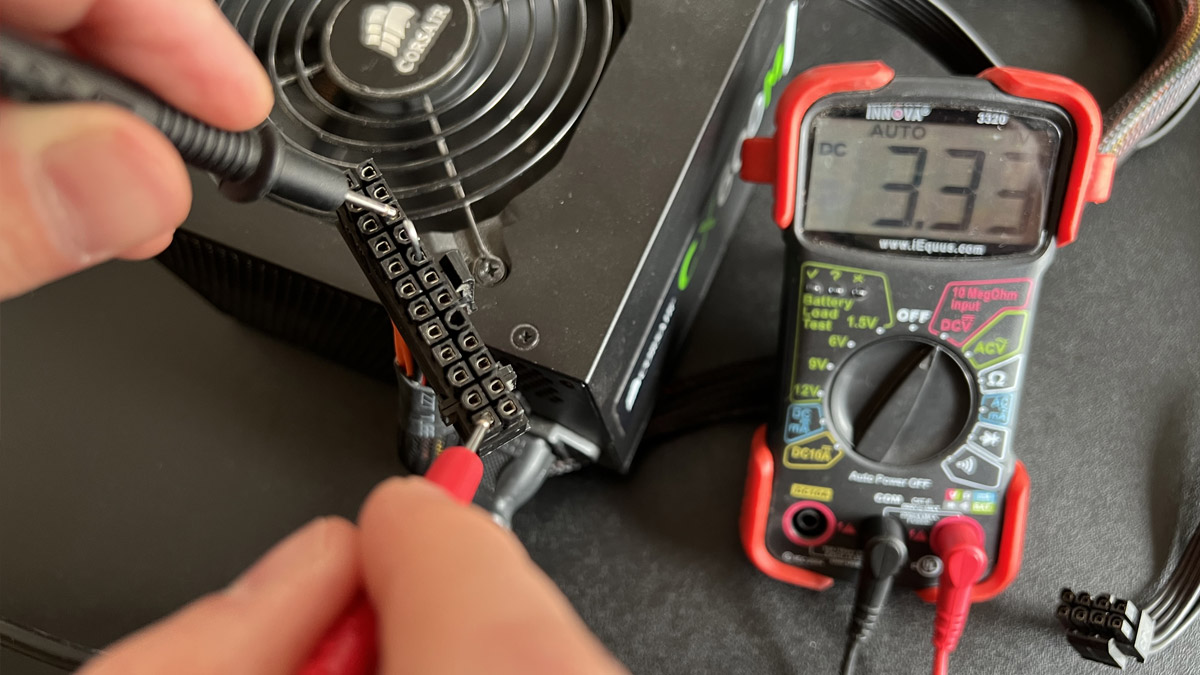
With the black probe on a grounded pin, touch it to any other pin and confirm that the reading is as expected.
For example, if you ground pin 15 and touch pin 24, the reading should be 3.3V (or within ±5% of 3.3V). You can see in the photo above that our 15-pin to 24-pin connection is dead with a 3.3V reading.
Repeat this process for all pins, confirming that the voltage reading is within the acceptable range. If the values are not within range, it is time to replace the power supply. Here’s the ATX power connection pinout again, for reference.
And here are the pinouts for the ATX/PCIe 8-pin (4 + 4), the ATX/PCIe 8-pin (6 + 2), and the Molex drive connector if you want to try those pins too.

As with the larger 24-pin power connector, simply ground the multimeter’s black probe to a known ground (either of the black pins above) and then touch the red probe to the other pins to check its voltage. You should check them for the same ±5% range.
In the interest of protecting your hardware, we’re not even going to suggest wiggle room parameters here. If one or more of the readings are outside of the ±5% range, simply replace the power supply and save yourself the headache that comes from a faulty power supply.
[ad_2]